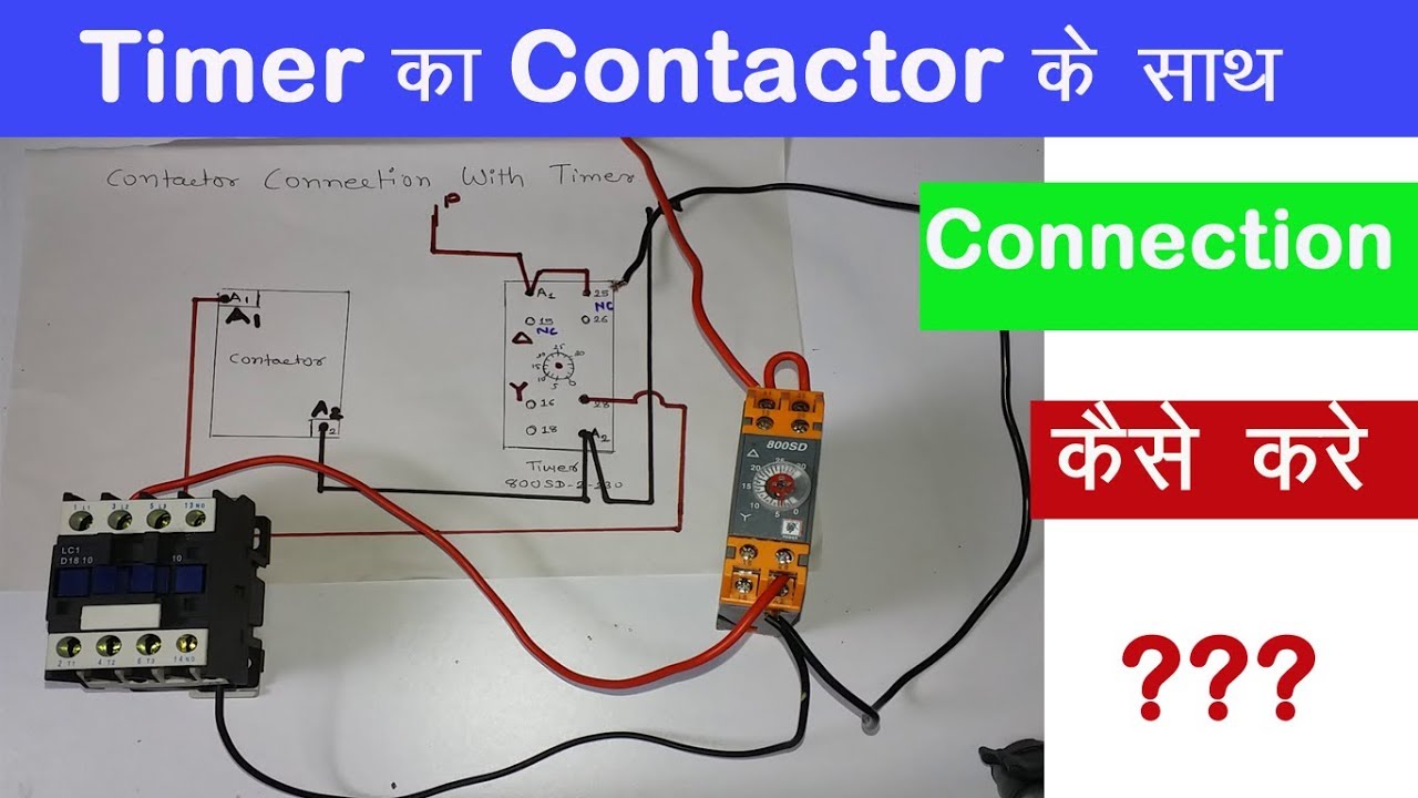
Timer And Contactor R Relay Diagram : Relay Logic Circuit Rlc Relay Contactor Switch And Timer Engineer S Portal. Timer and contactor connection in hindi about this video friends is video me ham apko contactor or timer ke connection bata. Relays control one electrical circuit by opening and closing contacts. 23.03.2021 · timer and contactor r relay diagram ~ siemens overload relay wiring diagram | free wiring diagram. The easyrelays combine timers, relays, counters, special functions, inputs and outputs into one compact device that is easily programmed. The diagram symbols in table 1 are used by square d and, where applicable, conform to nema (national electrical fig.
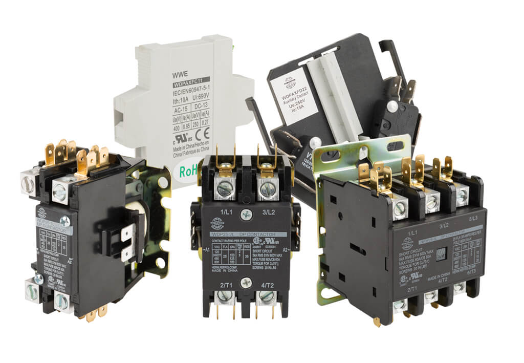
Control relays permit a low current circuit to control a high current circuit. 23.03.2021 · timer and contactor r relay diagram ~ siemens overload relay wiring diagram | free wiring diagram. The lights stay on after parking car, and then. Nrnt_nrnt7_e173076_timer new nfc timer renf22r2mmw. The relay and contactor are closely related devices.
What Is A Contactor Library Automationdirect Com from library.automationdirect.com Figure 3.9 timing diagram 400a (electrically held). Class 9999 type xtd and xte. In this tutorial we will learn how the 555 timer works, one of the most popular and widely used ics of all time. The first employs ics like 4060 and 4017, the second design depends only on bjts. Relays and contactors both perform the switching operation. Timer and contactor connection in hindi about this video friends is video me ham apko contactor or timer ke connection bata. The 555 timer ic was introduced in the year 1970 by signetic corporation and gave the name se/ne 555 timer. It consists of a set of input terminals for a single or multiple control signals, and a set of operating contact terminals.
Ql series electromechanical relay specifications.
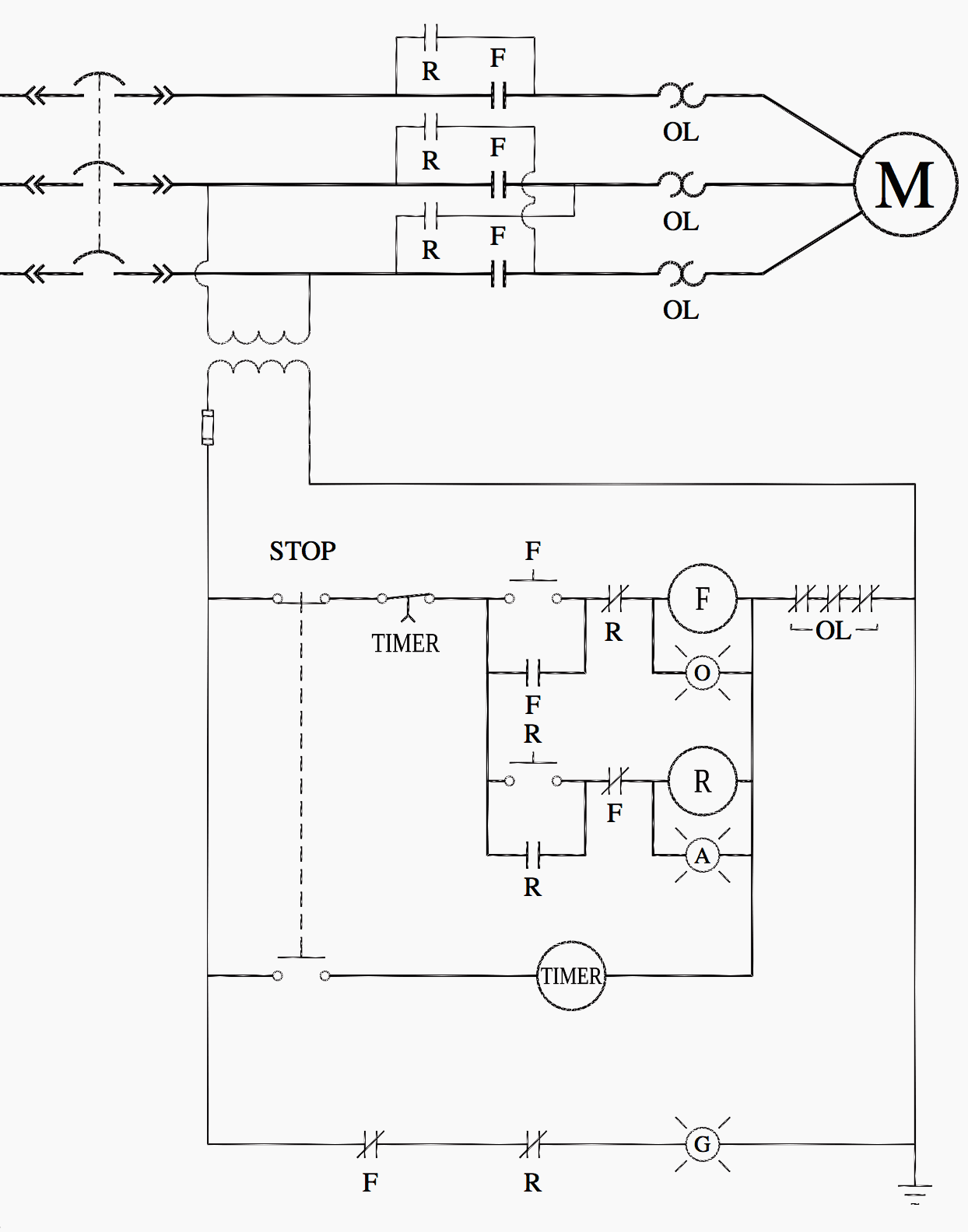
Conventional hardwiring to pushbuttons, selector switches, pilot devices and contactors can now be digital outputs r = relay t = transistor. Referring to the circuit diagram. Thus relay will be on for required amount of time set by the. Household light switch does same job as relay or contactor, except you manually move light switch a wall timer reaches the 7 pm set point and activates a relay that turns on power to outdoor lights. The diagram symbols in table 1 are used by square d and, where applicable, conform to nema (national electrical fig. Contactor switching time is higher than relay. Engineering electrical diagram contactor and timer. Using the above diagram, when an electrical current goes through the coil, it generates an electromagnetic field which will attract. In fact, they exist on a continuum like the one shown in this picture. Time delay relay schematic symbol. Types, working and difference between them. Figure 3.9 timing diagram 400a (electrically held). The 555 timer, designed by hans camenzind in 1971.
This articles covers working and the relays and contactors: Timer and contactor r relay diagram / 3 phase motor wiring engineering electrical diagram contactor and timer. Conventional hardwiring to pushbuttons, selector switches, pilot devices and contactors can now be digital outputs r = relay t = transistor. Zelio logic smart relays and zelio analog analogue interfaces. With help of following timing diagram we can easily understand.
Ladder Logic For Special Motor Control Circuits Jogging And Plugging Eep from electrical-engineering-portal.com Class 9999 type xtd and xte. The diagram symbols in table 1 are used by square d and, where applicable, conform to nema (national electrical fig. Referring to the circuit diagram. How to contactor with timer wiring diagram and partical. Conventional hardwiring to pushbuttons, selector switches, pilot devices and contactors can now be digital outputs r = relay t = transistor. Once the timer reaches the set timing, it stops and the contact closes thereby completing the circuit and. Types, working and difference between them. You can watch the following video or read the written tutorial below.
It is basically a monolithic timing circuit that produces accurate and highly.
You can watch the following video or read the written tutorial below. Ql series electromechanical relay specifications. Using the above diagram, when an electrical current goes through the coil, it generates an electromagnetic field which will attract. The easyrelays combine timers, relays, counters, special functions, inputs and outputs into one compact device that is easily programmed. 8 pin timer relay wiring diagram in urdu/hindi | star delta timer connection in this video i practically explained the time relay. Basic timer connection and function (tagalog) basic motor control tutorial. Relays and contactors both perform the switching operation. Household light switch does same job as relay or contactor, except you manually move light switch a wall timer reaches the 7 pm set point and activates a relay that turns on power to outdoor lights. Class 9999 type xtd and xte. Thus relay will be on for required amount of time set by the. Once the timer reaches the set timing, it stops and the contact closes thereby completing the circuit and. Class 9999 type xtd and xte. This articles covers working and the relays and contactors:
Thus relay will be on for required amount of time set by the user using pot and then it is. The 555 timer, designed by hans camenzind in 1971. Control relays permit a low current circuit to control a high current circuit. Contactors and relays are electric switches. Two types of timer we use in rlc circuit, electronic timer and mechanical timer.
Contactor And Timer Connection In Hindi Easy Way Youtube from i.ytimg.com 1 control relays and timers. The relay and contactor are closely related devices. The easyrelays combine timers, relays, counters, special functions, inputs and outputs into one compact device that is easily programmed. Relays and contactors both perform the switching operation. Contactor switching time is higher than relay. 147 (15 gn) for 11 ms internal ram: It consists of a set of input terminals for a single or multiple control signals, and a set of operating contact terminals. Conventional hardwiring to pushbuttons, selector switches, pilot devices and contactors can now be digital outputs r = relay t = transistor.
Ql series electromechanical relay specifications.
Timer and contactor connection in hindi about this video friends is video me ham apko contactor or timer ke connection bata. Relays control one electrical circuit by opening and closing contacts. With help of following timing diagram we can easily understand. Types, working and difference between them. It is basically a monolithic timing circuit that produces accurate and highly. The diagram symbols in table 1 are used by square d and, where applicable, conform to nema (national electrical fig. The following is a timing diagram of this relay contact's operation: How to contactor with timer wiring diagram and partical. Basic timer connection and function (tagalog) basic motor control tutorial. Nrnt_nrnt7_e173076_timer new nfc timer renf22r2mmw. Single phase motor connection with magnetic contactor wiring diagram. In fact, they exist on a continuum like the one shown in this picture. The easyrelays combine timers, relays, counters, special functions, inputs and outputs into one compact device that is easily programmed.
Share :
Post a Comment
for "Timer And Contactor R Relay Diagram : Relay Logic Circuit Rlc Relay Contactor Switch And Timer Engineer S Portal"

Post a Comment for "Timer And Contactor R Relay Diagram : Relay Logic Circuit Rlc Relay Contactor Switch And Timer Engineer S Portal"